DDC stands for Direct Digital Control. It is a control system technology used in commercial HVAC applications, such as chiller plants, condenser water systems, variable air volume (VAV) systems, VAV boxes, fan coil units, and more. These HVAC applications require sophisticated control devices that can effectively manage their sequence of operations while enabling remote monitoring and supervision. These devices, known as DDC controllers, are considered the “brain” of HVAC systems in large facilities and commercial applications.
What is Direct Digital Control (DDC)?
Direct Digital Control is a control technology that uses digital microcontrollers to automatically manage processes like temperature and pressure or respond to specific conditions (logic). Widely adopted by the HVAC industry, DDC technology enables precise control along with features such as programmability, network connectivity, data exchange, and remote management.
Components of DDC Control Systems
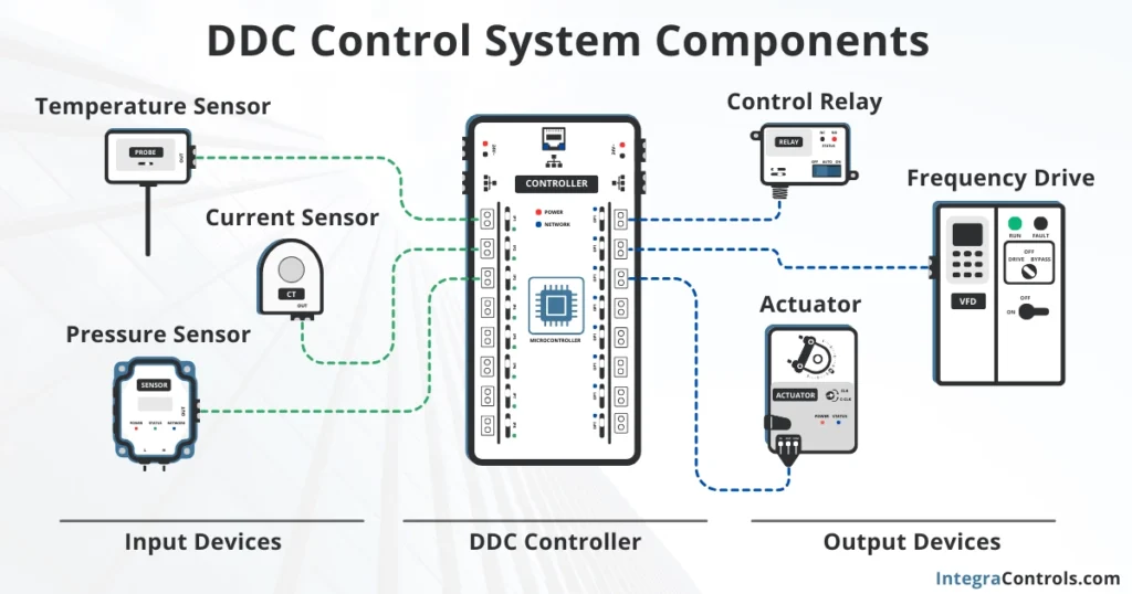
A complete DDC-based control system consists of three main components: input devices, DDC controllers, and output devices.
DDC System Input Devices
The input devices in a DDC-controlled HVAC application are typically sensors such as those measuring temperature, humidity, CO2, static pressure, flow, current, and switches. The output signals from these sensors vary by manufacturer but generally include 0 to 5 volts, 0 to 10 volts, 4 to 20 mA, or resistive signals (e.g., 10 KΩ for temperature). These sensor outputs are connected to the DDC controller inputs via control wiring.
DDC Controller
The DDC controller is where the program or sequence of operation (SOO) for the HVAC equipment resides. The controller reads sensor signals and, based on a pre-defined internal logic, makes decisions that are then translated into output signals sent to the output devices. The signals produced by the DDC controller are typically 0 to 10 volts DC, 24 volts AC, or open/close contacts.
DDC System Output Devices
The output devices in a DDC-controlled HVAC application include relays, actuators, drives, and other controllers’ inputs. These devices drive the operation of HVAC equipment, such as starting or stopping blower motors and compressors, and controlling dampers, valves, and fan speed modulation. Output devices also provide isolation, protecting the DDC controller from direct interaction with high-voltage components like motor and compressor electrical contacts, thus safeguarding the controller from electric surges and interference.
How DDC Controllers Work
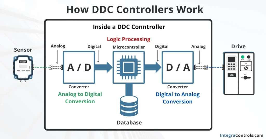
DDC controllers typically follow a three-step process to control a specific variable (e.g., temperature, pressure) and drive an output. These steps are: analog to digital conversion, logic processing, and digital to analog conversion.
Analog to Digital Conversion
DDC controllers are inherently digital, meaning all processing takes place through a digital microcontroller that only understands digital signals or bits of data. Even though the controller reads analog sensors, it cannot interpret analog signals directly. The controller must convert the analog signals into a digital format before it can process them and make a decision.
Logic Processing
A DDC controller constantly reads data and makes decisions based on pre-designed logic. This logic is designed to respond to the sequence of operations for the application, process, or equipment being controlled.
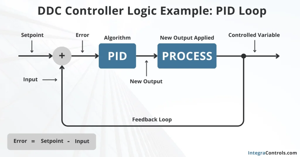
The logic processing in a DDC controller is carried out by digital microcontrollers. The most common control logics in HVAC applications are typically PID loops used to control processes at a fixed setpoint, time-sensitive binary logics such as occupancy schedules for start-stop sequences, and load demand logics to drive compressors, valves, and fan speeds, to name a few. The microcontroller generates digital signals as a response to the inputs and the existing logic.
Digital to Analog Conversion
All output digital signals generated by the microcontrollers inside a DDC controller must be converted back to analog signals before they can be sent to the actual controller outputs and drive the output devices. This conversion is done internally through digital-to-analog converter blocks that feed each output of the controller. For instance, analog outputs (AO) typically produce a signal from 0 to 10 volts DC, while binary outputs (BO) produce a 0/24 volts AC signal. Both are analog signals.
Example of DDC Controls in HVAC
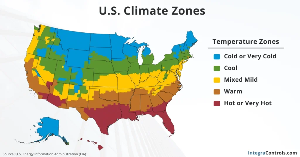
As mentioned, each HVAC application has its own particularities, and the final operation will depend on the design intended by the engineers, the climate zone, and building codes and regulation requirements. To fully understand the operation of a specific HVAC system, we must read its sequence of operation (SOO), which will allow us to identify the inputs, outputs, logic, and setpoints required for the application.
Fan Coil Unit – DDC Controls
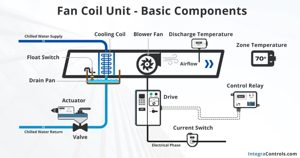
Fan coil units (FCU) are very common in commercial HVAC applications, and their sequence of operation is typically very basic. The main mechanical components of a fan coil unit are a variable blower fan and an evaporator coil. For this example, we will use a chilled water fan coil unit for illustration purposes.
Fan Coil Unit – Basic Sequence of Operation
As mentioned earlier, the sequence of operation (SOO) provides the information that allows us to extract the inputs, outputs, logic, and setpoints required for the HVAC control application. We have simplified the SOO to make it easy to understand. In this example, we will use a basic sequence of operation for a cooling-only chilled water fan coil unit with a variable-speed fan, driven by an occupancy schedule, with no humidity or ventilation control.
Unit Start-Stop: The unit shall start and stop as per the zone occupancy schedule.
Valve Control: In cooling mode, the valve shall modulate to maintain a discharge air temperature of 55 °F. In heating mode, the valve shall modulate to maintain a discharge air temperature of 60 °F.
Fan Speed Control: The fan speed shall modulate based on the zone’s cooling or heating demand.
Safety Features: The unit shall shut down if excessive water buildup is detected in the drain pan. The unit shall also shut down if fan status is lost for more than two minutes. An alarm event shall be triggered anytime the unit shuts down due to a safety override.
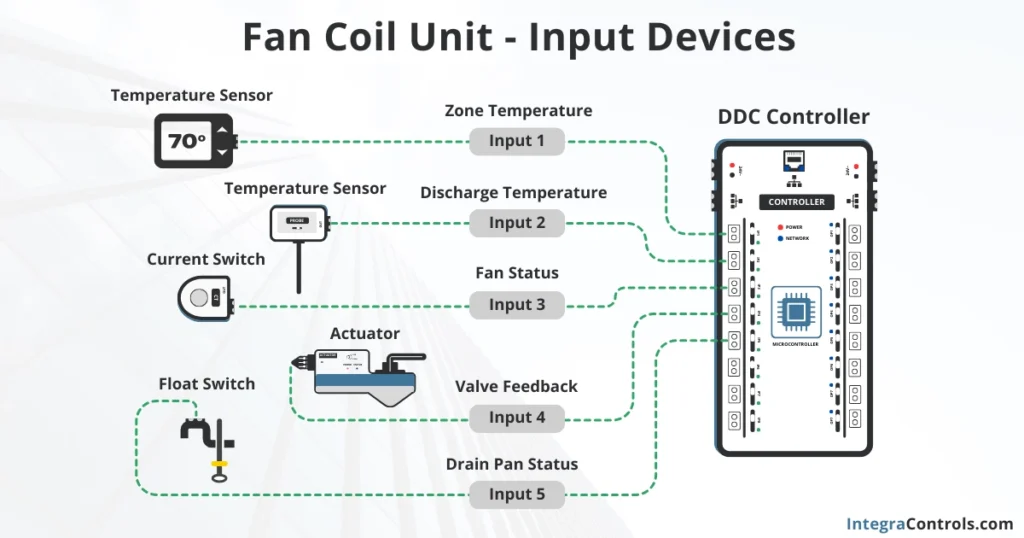
Fan Coil Unit – Input Devices
The sensors and switches that must be connected to the inputs of the fan coil unit’s DDC controller are:
- Zone Temperature (controlled variable): A zone temperature sensor is required.
- Discharge Air Temperature (controlled variable): A temperature sensor is needed in the discharge.
- Drain Pan Status (safety): A float switch sensor must be installed in the drain pan.
- Fan Status (safety): A current transducer or current switch is required to monitor fan status.
- Valve Feedback (monitoring): A valve-actuator with position feedback is needed.
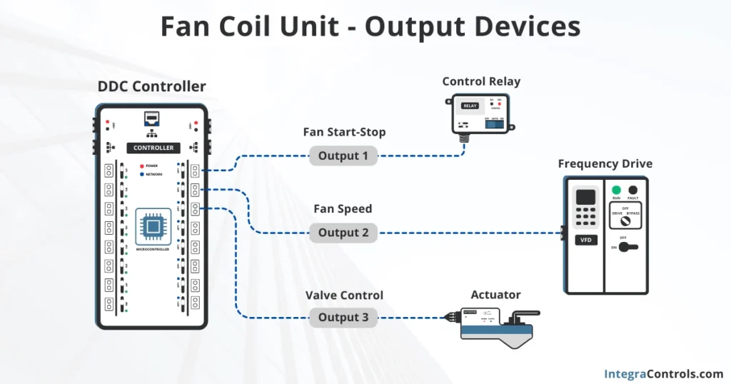
Fan Coil Unit – Output Devices
The relays, actuators, and other modules that must be connected to the outputs of the fan coil unit’s DDC controller are:
- Fan Start-Stop: A relay may be needed to control the fan coil motor.
- Fan Speed: A speed signal may need to be sent to a frequency drive or input module to provide a speed reference for the FCU blower fan.
- Valve Control: A valve-actuator or position reference signal must be provided.
Fan Coil Unit – Controller Logic
The programming logic required in the DDC controller to meet the sequence of operation should include:
- Fan Start-Stop: Governed by binary logic based on the occupancy schedule, there must be an internal schedule controlling the unit’s start-stop logic.
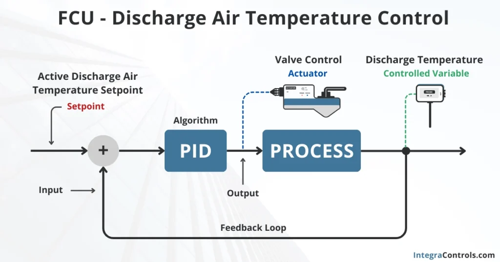
- Valve Control: Requires PID loop logic. A control loop will regulate discharge air temperature based on the unit’s operating mode (cooling or heating). Discharge air temperature setpoints for both modes must be defined.
- Fan Speed Control: Speed control is based on zone demand, which requires two PIDs to manage cooling and heating demands. Zone heating and cooling setpoints must be created. This calculation will also determine the unit’s operating mode (cooling or heating).
- Safety Override: Operation should be interrupted if certain conditions occur: the drain pan float switch is activated, or fan status is lost for more than two minutes. This is an example of override sequence logic, which takes priority over the unit’s normal operation.
Fan Coil Unit – Operational Setpoints
These are some of the required setpoints for the FCU application:
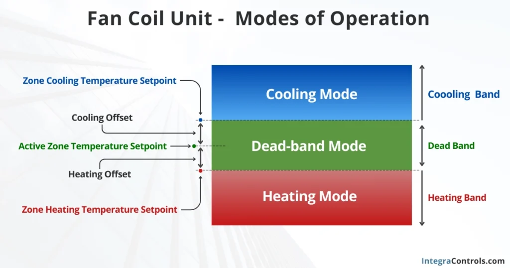
- Zone Cooling Temperature Setpoint: When the temperature rises above this setpoint, the fan coil unit will enter cooling mode.
- Zone Heating Temperature Setpoint: When the temperature drops below this setpoint, the fan coil unit will enter heating mode.
- Active Zone Temperature Setpoint: The desired zone temperature. This setpoint will be between the heating and cooling setpoints, with offset values set for both.
- Heating Discharge Air Temperature Setpoint: The target discharge temperature in heating mode (e.g., 60 °F).
- Cooling Discharge Air Temperature Setpoint: The target discharge temperature in cooling mode (e.g., 55 °F).
- Active Discharge Air Temperature Setpoint: This will take the value of either the heating or cooling discharge air temperature setpoint, depending on the unit’s operating mode (cooling or heating). This setpoint will feed into a PID loop to control valve position.
Additionally, the application should include objects such as an occupancy schedule and alarm events to notify when the unit’s operation is interrupted, or faults are detected.
This describes the first step in the four-step process of implementing HVAC DDC controls. In the next section, we will cover the following steps.
HVAC DDC Controls Implementation Steps
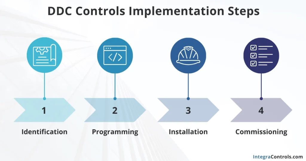
The complete implementation of DDC controls in HVAC systems can be broken down into a four-step process: identification, programming, installation, and commissioning.
System Identification
In the identification phase, we determine the HVAC application being implemented. This requires reviewing the sequence of operations (SOO), as explained in the prior section, and identifying the inputs, outputs, logic, and setpoints for the application. In many cases, there are no available references for the SOO, making it necessary to perform a site walkthrough and system takeoff. This is common for existing facilities, system upgrades, and retrofit projects.
System Programming
The HVAC control programmer gathers all the information from the sequence of operations and writes a program into the DDC controller to fit the entire operation. As part of this process, the control engineers must carefully select the proper DDC controller with the capacity to handle the required inputs and outputs for the application.
System Installation
The HVAC control technician and installers deploy the application in the field. This includes running wires, conduits, and communication cables, as well as installing the control panel, sensors, actuators, and other field devices required for the application. All input and output devices are connected to the DDC controller according to the specifications provided by the programmer or controls engineer who wrote the program and created the HVAC control submittals.
System Commissioning
During the commissioning process, the HVAC control panel is powered up, and a point-to-point inspection is performed. All inputs should display realistic values, and it is necessary to take readings with meters to ensure that the inputs are accurate. Output devices should be tested one by one, verifying that they operate as intended and control the mechanical components (valves, dampers, frequency drives, etc.) correctly.
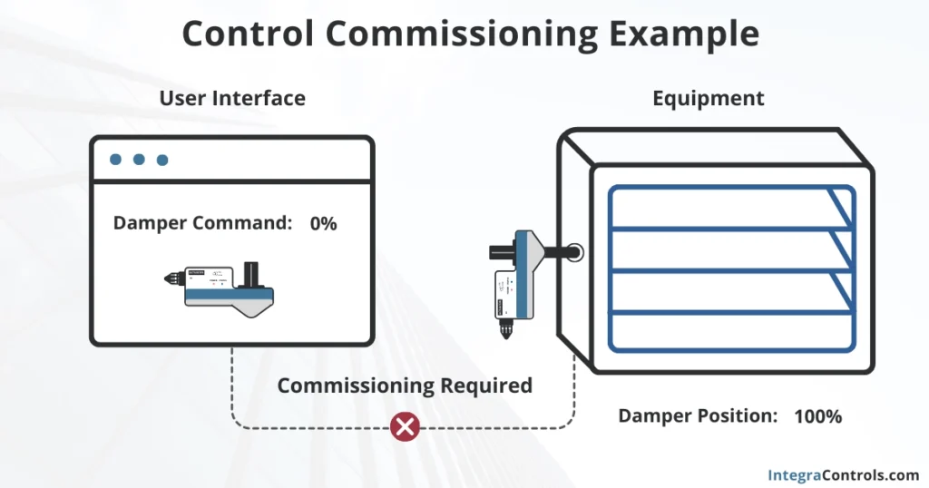
A good practice during commissioning is to modify the setpoints to confirm that the PID loops are adjusting accordingly. Finally, the HVAC DDC controller should be set to auto mode and monitored for a few days to ensure the system is operating as intended. Setting up historical trends is an efficient way to track performance.
Applications of DDC in Building Management
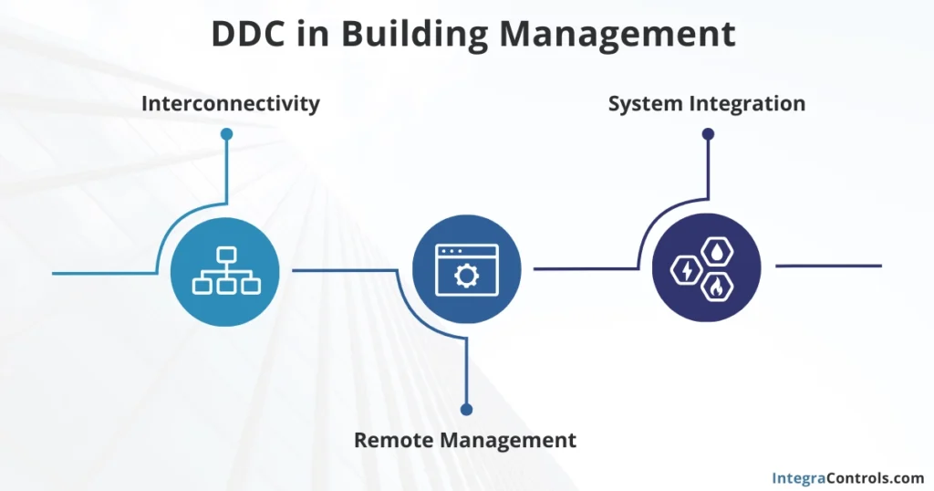
Direct Digital Control (DDC) systems are a key component of smart building infrastructure in modern facilities, enabling interconnectivity, remote management, and system integration.
Interconnectivity
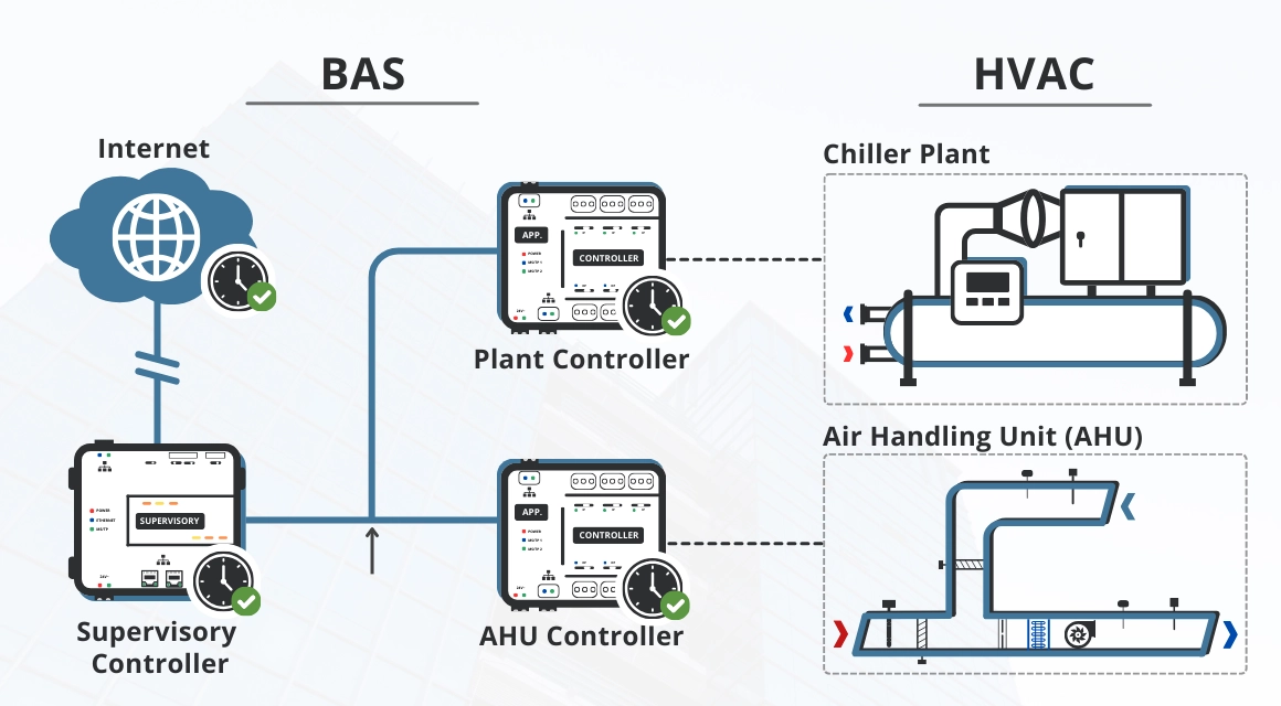
DDC controllers can operate as standalone devices when controlling an HVAC application, such as an air handling unit or a fan coil. However, in most cases, they are interconnected into a network known as a Building Automation System (BAS). Through the BAS network, DDC controllers can exchange data with each other, such as occupancy schedules, load demand, alarms, and more.
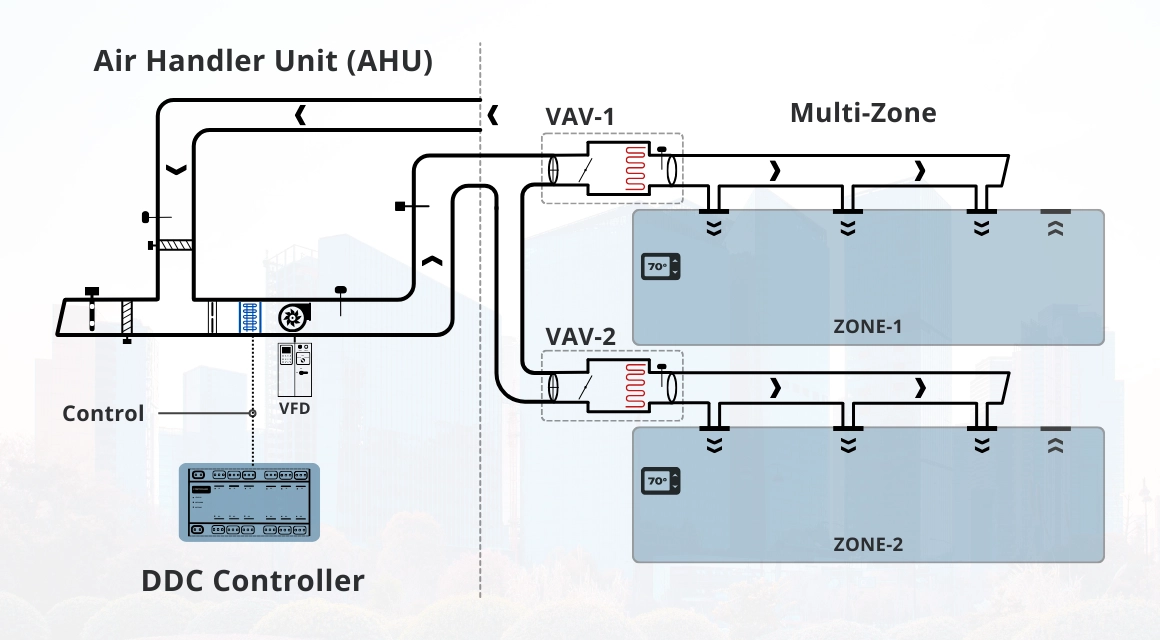
This communication helps improve overall system operation and efficiency. A typical example of this is a multizone variable air volume (VAV) system, where VAV boxes share load demand information with the main air handling unit, allowing it to adjust operational setpoints, improving comfort and eliminating unnecessary energy waste.
Remote Management
Network connectivity among DDC controllers also enables remote management through a front-end portal, commonly referred to as a Building Management System (BMS). Through the BMS, building operators can visualize HVAC equipment in a user-friendly interface, enabling equipment monitoring, setpoint adjustments, scheduling, fault detection, energy management, and visualization of historical trends.
System Integration
Although DDC controllers are commonly used for HVAC applications, their potential for controlling and supervising other building systems is growing very quickly.
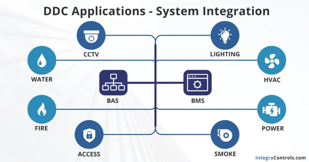
Due to the interconnected nature of DDC devices, many building operators choose to integrate various other systems into the BAS network, such as domestic water systems, emergency generators, smoke evacuation systems, transfer power switches, lighting systems, and more. This integration allows operators to access all systems from a single location, improving visibility and oversight of building assets.
Benefits of DDC Systems
DDC systems offer numerous benefits to building owners, facility operators, and enterprises. These benefits include:
Centralized Smart Building Infrastructure: DDC controllers form the foundation of smart building infrastructure in commercial facilities, interconnected within a single network known as a building automation system (BAS).
Remote Management: DDC systems can be remotely accessed through a user interface called a building management system (BMS), enabling operators to monitor and control HVAC equipment and other integrated systems.
System Integration: Most DDC controllers use standard communication protocols such as BACnet® and Modbus®, allowing the integration of additional systems into the BAS network. This provides building operators with greater visibility and awareness of the status of multiple building systems.
Early Fault Detection: Intelligent algorithms can be programmed into DDC controllers to alert operators to developing system faults before they escalate into complete failures or interruptions.
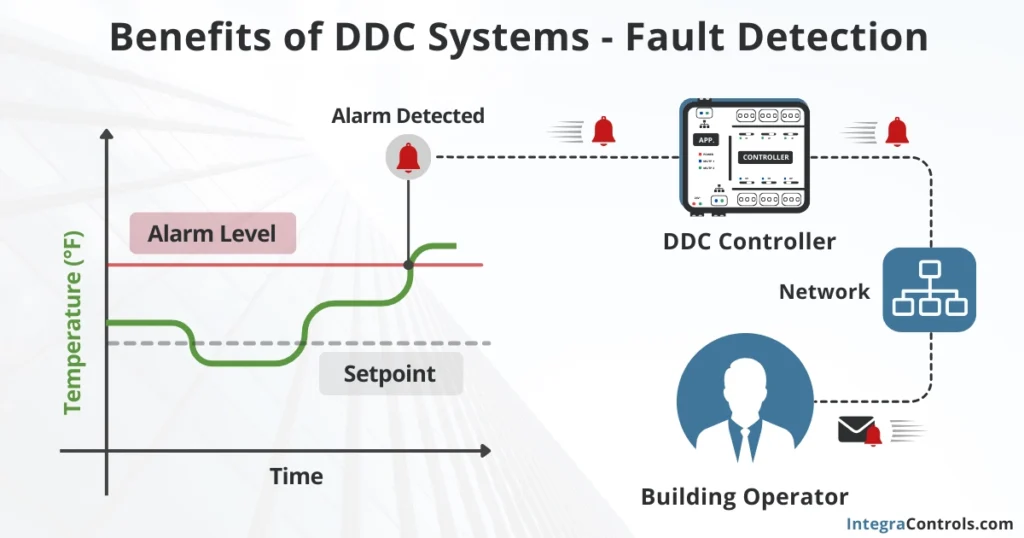
Rapid Response to Failures: DDC systems can quickly notify operators about critical failures and potential interruptions, significantly reducing response times and helping to address problems promptly.
Energy Management: HVAC DDC controllers enable energy management practices in large facilities and enterprises, helping to eliminate energy waste and drive large-scale energy savings.
Improved Energy Efficiency: DDC controllers are programmable, meaning their internal programs can be modified to implement HVAC energy optimization practices, reducing power consumption and generating energy savings.
Disadvantages of DDC Systems
Implementing DDC technology brings many benefits to facility management and operations; however, it also has some drawbacks that should be considered:
Implementation Cost: Integrating DDC technology into a new facility is not inexpensive. This typically requires an assessment from a BAS consultant who will gather all the information needed for the upgrade. Most organizations choose to upgrade their old HVAC control systems (typically pneumatic controls) to DDC gradually, on a one-by-one equipment basis. This approach helps avoid operational disruption and also spreads out the costs by depreciating the investment as a capital expenditure (Capex). Despite the cost of implementation, savings in energy consumption often begin the same day the DDC system is installed.
System Complexity: Most people understand that regular HVAC applications typically focus on temperature control. However, commercial HVAC systems driven by DDC controls do more than just regulate temperature; they also manage other variables such as building ventilation, CO2 levels, relative humidity, and static pressure. These additional variables make commercial HVAC systems much more complex, requiring more training and experience to operate and maintain them properly.
System Inspection and Maintenance: DDC systems operate effectively only when their logic and components are functioning correctly. Regular system inspections are recommended to verify that there are no faulty components or malfunctioning sequences. Additionally, some HVAC control components require calibration, exercise, and maintenance to ensure accurate readings and optimal system performance.
Inspection and Maintenance of DDC Systems
As we mentioned before, DDC systems need regular inspections and maintenance to keep the HVAC system operating at optimal performance. Here are the most common practices to ensure your DDC systems remain reliable and in proper condition:
Input Status Verification: Verify the input readings to ensure they display values that make sense. This helps detect faulty sensors (temperature, CO2, etc.) and wiring issues.
Outputs Operation Verification: Confirm that the outputs are properly driving the mechanical/electrical components as intended. This will highlight any loose wiring connections or malfunctioning components.
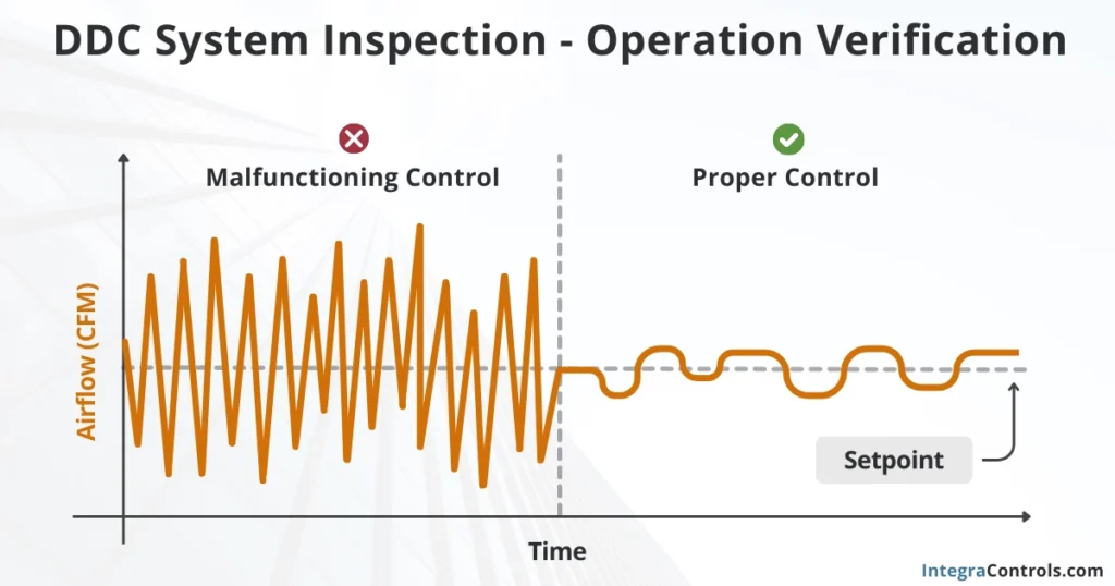
Sequence of Operation Verification: With the help of historical trends, we can visualize the past and recent operation of the unit and verify if it is functioning as designed. In most cases, this sequence of operation (SOO) verification reveals incomplete logic, bugs, and errors that were not detected during the commissioning process.
DDC Controller Database Backup: The database of the DDC controller should be backed up and sent to the client after each inspection. This is a good practice that ensures if the DDC controller is damaged in the future, we have a copy of the last database, allowing for faster restoration of equipment operation.
These are the typical checklist points that most HVAC control contractors offer to their clients. However, a more comprehensive HVAC control service agreement that ensures better system performance and long-term energy savings should also include:
Inputs Recalibration: Verify the readings of sensors against calibrated meters to ensure they are reading accurately. This is especially recommended for controlled variables that are part of a PID loop, such as discharge air temperatures, duct static pressure, and CO2 sensors.
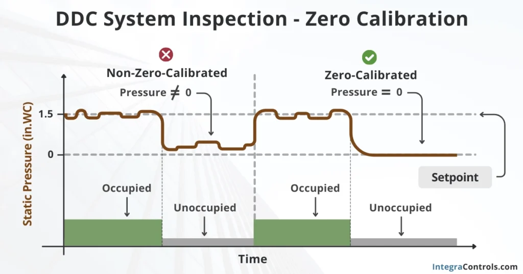
Inputs Zero Calibration Correction: Zero calibration ensures that sensors read zero when they should. This is accomplished by correcting their values when the zero-reading environment is present. Static pressure, air velocity, and airflow sensors typically require zero calibration.
Sensors Cleaning: Some sensors accumulate dust and debris and may eventually stop reading accurately. These sensors must be properly cleaned to restore their functionality, particularly airflow sensors.
Dampers and Actuators Maintenance: Dampers and actuators require particular attention during verification and maintenance. These components are often exposed to critical environmental conditions such as high pressure, extreme temperature swings, and high relative humidity levels, making them some of the first components to fail in an HVAC system. This typically occurs because they get stuck due to lack of exercise. However, the operation of dampers and actuators can be restored through proper exercising and regular cleaning and greasing.
Energy Optimization: DDC controllers are programmable devices, allowing for additional energy efficiency strategies to be programmed into the controller. This can help reduce the overall base power demand and consumption of the HVAC equipment, eliminating energy waste and driving energy savings.
In Summary
Direct Digital Control (DDC) systems represent a transformative leap in HVAC technology, offering unparalleled precision and efficiency in managing complex building environments. By utilizing digital microcontrollers, DDC systems enable automated, responsive control of HVAC operations, ensuring optimal temperature, pressure, and airflow throughout commercial facilities.
The architecture of DDC systems—including input devices, controllers, and output devices—facilitates real-time data monitoring and decision-making, enhancing energy management and operational efficiency. As part of a Building Automation System (BAS), DDC controllers can communicate with various building systems, creating an integrated network that improves overall building performance.
While DDC systems bring substantial benefits, such as centralized control, early fault detection, and enhanced energy savings, they also introduce complexities that require careful implementation, regular maintenance, and skilled personnel. Building operators must navigate the upfront costs and ongoing system inspections to maintain the high performance of these sophisticated systems.
Ultimately, the adoption of DDC technology in HVAC applications not only optimizes energy consumption and operational efficiency but also positions facilities for a more sustainable and interconnected future in smart building management.
